Variable Rf Attenuator Circuit
Variable Pin Diode Attenuator Daycounter

Rf Attenuators Digikey

Schematics Com Low Insertion Loss Voltage Variable Attenuator Circuit

Bridged T Attenuator Tutorial For Passive Attenuators

Potentiometer Is A Three Terminal Variable Resistor Which Acts As An Adjustable Voltage Divider It Is Used I Voltage Divider Electronics Circuit Circuitry

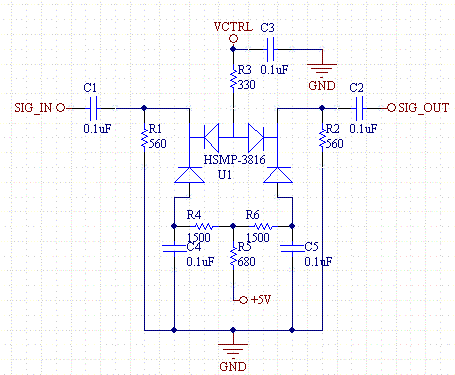
Diode Quad Is Foundation For Pin Diode Attenuator Microwaves Rf

Typically variable attenuators provide a continuous level change by varying an analogue voltage on the input control line.
Variable rf attenuator circuit.

Colpitts Lcoscillator Is An Electronic Circuit That Produces A Periodic Oscillating Electronic Si Electronics Circuit Electronics Projects Electric Circuit

Waveguide Shorting Plates Provide An Almost Perfect Rf Reflection In A Waveguide System Electronics Collection Of L Electronics Projects Electronics Reflection

The Depletion Mode Has Negative Gate Operation This Decreases The Width Of The Depletionlayer Electronics Circuit Depletion Region Electronics

Schematics Com Search Results
Source : pinterest.com
